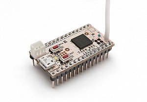
Unveil your imagination to create:
- battery powered in-wall remote switch
- rotary dimmer control
- temperature/soil humidity/luminosity/voltage/distance or any other sensors as well as dry contact sensor or tick counter
- low voltage switch
- IR blaster
- LED driver
- motor driver
- battery powered keypad
- converter from any protocol to Z-Wave (using SPI/UART/I2C/1-wire bus)
- ... or any other device you dreamed about
Make your own Z-Wave device:
- control any Arduino compatible peripherals
- define your own logic by modifying your sketch
- use Arduino IDE and language to write and upload sketches
- easy to use
- requires no knowledge of Z-Wave protocol
- complete DIY solution
Hardware specification:
- 28 kB Flash memory for your sketches
- 174 kB Flash memory for your sketches
- 2 kB RAM available
- 16 kB RAM available
- Z-Wave RF transmitter at 9.6/40/100 kbps
- Long Range
- 26 GPIO (overlaps with special hardware controllers)
- 4 ADC
- 5 PWM
- 4 PWM
- 2 UART
- 1 USB (serial port)
- 16 kB EEPROM
- 3 kB pseudo EEPROM
- 1 SPI (master or slave)
- 4 IR controllers, 1 IR learn capability
- 1 TRIAC/ZEROX to control dimmer
- 3 Interrupts
- 6 Interrupts
- 1 Timer 4 MHz
- 3 Timers
- I2C (software)
- 1-Wire (software)
- 8x6 Keypad Scanner (software)
- 2 service LED, 1 service button
- 1 user test LED
Power modes:
- USB 5 V, external 5 or 3 V, external 7-18 V or battery (via MU-2F connector, included)
- USB 5 V, external 5 or 3 V, external 7-18 V or battery
- always on, sleeping or FLiRS (Frequently Listening)
Z-Wave supported features:
- Z-Wave Plus compliant
- all Z-Wave frequencies (check availability)
- out of the box support of AES 128 bit Security (S0 and S2)
- 2 × Hardware Cryptographic Acceleration for AES 128/256, SHA-1, SHA-2 (SHA-224 and SHA-256) and ECC
- upgrade via USB or radio (Z-Wave OTA)
- Multichannel (32 channels)
- 5 Association groups
- controls switches, dimmers, door locks and scenes
- works with gateways and/or directly with other Z-Wave devices
Channel types:
- Binary Switch
- Multilevel Switch
- Color Switch
- Binary Sensor
- Multilevel Sensor
- Meter
- Door Lock
- Water Valve
- Siren
- Thermostat
- Flow Stop
- Switch Color
- Blinds
Dimensions:
- L×W×H: 39×20×16 mm (PCB dimentions with all components)
- L×W×H: 39×20×7 mm (PCB dimentions with PLS and battery connectors removed)
- L×W×H: 39×20×14 mm (PCB dimentions with all components)
- L×W×H: 39×20×6 mm (PCB dimentions with PLS removed)
- Antenna lenght: 86 mm (89 mm with isolation), can be bent to better fit your dimensions
- Antenna lenght: 115 mm (118 mm with isolation), can be bent to better fit your dimensions
- Weigth: 7 g
Antenna:
- Antenna type: wire antenna 86 mm for 865-870 MhZ
- Antenna type: wire antenna 115 mm for 865-925 MhZ
- Alternative antenna: optional u.fl connector can be soldered (to RF2 pads)
Electrical characteristics:
- Digital pin in logical 1: > 2.1 V, leakage current 10 μA
- Digital pin in logical 0: < 0.9 V, leakage current 10 μA or 40–120 μA (with internal pull-up enabled)
- All GPIO pins except PB14 and PB15, Input leakage current 30nA max
- Internal pullup resistor: 15–20 kΩ (at +25°C)
- Internal pullup resistor: 65 kΩ max (at +25°C)
- Digital pin out logical 1: > 2.4 V, max current sourcing 8 mA (16 mA for digital pins 3-6)
- Digital pin out logical 1: > 2.4 V, max current sourcing 50 mA
- Digital pin out logical 0: < 0.4 V, max current sinking 8 mA (16 mA for digital pins 3-6)
- Digital pin out logical 0: < 0.4 V, max current sinking 50 mA
- Total max current sourcing from GPIO pins: 120 mA
- Total max current sourcing from GPIO pins: 200 mA
- Power consumption on 3.3 V:
- in always listening mode 50 mA
- in always listening mode 7 mA
- in sleep mode 1 mA (about 7 μA if DC-DC is turned off by unsoldering R12)
- in sleep mode EM4 9 μA (about 1 μA if DC-DC is turned off by unsoldering R12)
- in FLiRS mode 1 mA (about 70 μA if DC-DC is turned off by unsoldering R12)
- Power consumption on 5 V: in always listening mode ∼ 30 mA (can be lowered by using external switching DC-DC)
- Power consumption on 5 V: in always listening mode ∼ 13 mA (can be lowered by using external switching DC-DC)
- Power consumption on 7–18 V: in always listening mode ∼ 35 mA (can be lowered by using external switching DC-DC)
- Power consumption on 7–18 V: in always listening mode ∼ 10 mA (can be lowered by using external switching DC-DC)
- DC-DC installed:
- 7–18 V → 5 V: NCP1117ST50T3G, max current sourcing from 5V pin 400 mA
- 5 V → 3 V: MCP1700, max current sourcing from 3V pin 150 mA
See Z-Uno power supply schematics for more info.
Pinout
CAD libraries
Download  Fritzing,
  Eagle1 and
  KiCAD2 part files.
1 — community contribution by user schmidmi. 2 — community contribution by user droll.
Deeper insight
Know more about Z-Uno internals.
