/*
*
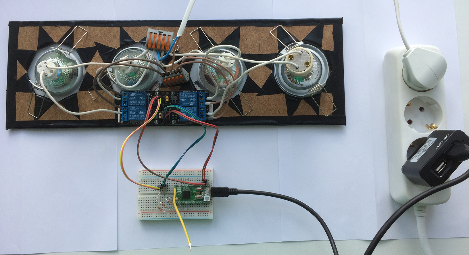
* 4 Relays controlled thouth resistors 220Omh and optocouplers 817С
* Off - HIGH
* On - LOW
*/
// Pins definitions
#define LedPin1 9
#define LedPin2 10
#define LedPin3 11
#define LedPin4 12
// Global variables to store data reported via getters
byte switchValue1 = 1;
byte switchValue2 = 1;
byte switchValue3 = 1;
byte switchValue4 = 1;
ZUNO_SETUP_SLEEPING_MODE(ZUNO_SLEEPING_MODE_ALWAYS_AWAKE);
// Set up 10 channels
ZUNO_SETUP_CHANNELS(
ZUNO_SWITCH_BINARY(getterSwitch1, setterSwitch1),
ZUNO_SWITCH_BINARY(getterSwitch2, setterSwitch2),
ZUNO_SWITCH_BINARY(getterSwitch3, setterSwitch3),
ZUNO_SWITCH_BINARY(getterSwitch4, setterSwitch4)
);
void setup() {
// set up I/O pins. Analog and PWM will be automatically set up on analogRead/analogWrite functions call
pinMode(LedPin1, OUTPUT);
pinMode(LedPin2, OUTPUT);
pinMode(LedPin3, OUTPUT);
pinMode(LedPin4, OUTPUT);
}
void loop() {
// Empty
}
// Getters and setters
void setterSwitch1(byte value) {
digitalWrite(LedPin1, (value > 0) ? LOW : HIGH);
switchValue1 = value;
}
byte getterSwitch1(){
return switchValue1;
}
void setterSwitch2(byte value) {
digitalWrite(LedPin2, (value > 0) ? LOW : HIGH);
switchValue2 = value;
}
byte getterSwitch2(){
return switchValue2;
}
void setterSwitch3(byte value) {
digitalWrite(LedPin3, (value > 0) ? LOW : HIGH);
switchValue3 = value;
}
byte getterSwitch3(){
return switchValue3;
}
void setterSwitch4(byte value) {
digitalWrite(LedPin4, (value > 0) ? LOW : HIGH);
switchValue4 = value;
}
byte getterSwitch4(){
return switchValue4;
}
 Link to detailed project description (in Russian, use Google to translate)