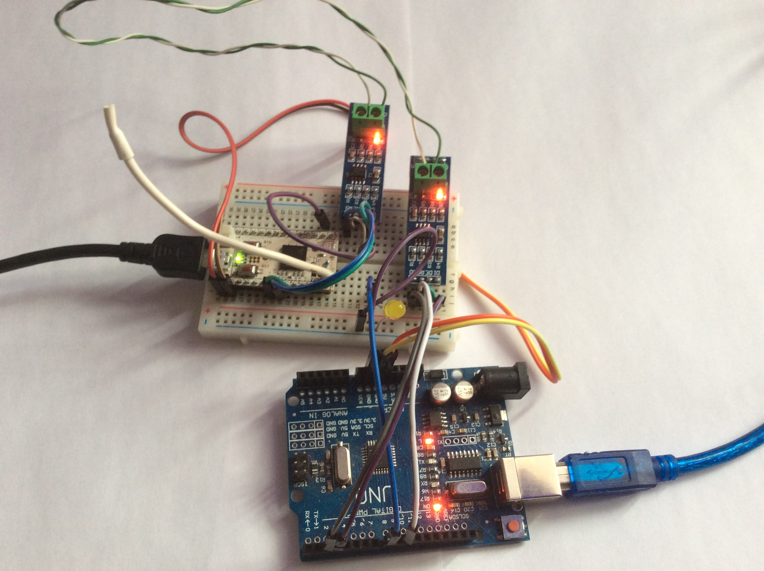
RS-485 bus based on MAX485 Chip
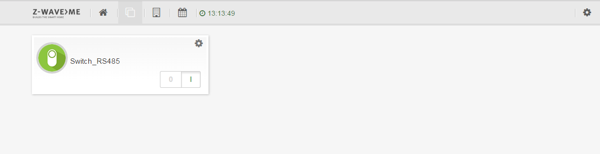
Example of RS-485 bus communications using MAX485 chip. Z-Uno Switch Binary channel state is sent via RS485 bus to a slave device based on Arduino Uno.
Download Fritzing project
// demo sketch connecting Z-Uno to the RS485 network and sending commands to slave device (Arduino Uno) the status of the Switch Binary channel

// set up channel
ZUNO_SETUP_CHANNELS(
      ZUNO_SWITCH_BINARY(getter, setter)
);

// pin for send/get rs485
int pin_direction_RX_TX = 10;
// address slave device arduino uno
int address = 1;
// status SWITCH BINARY
int statusswitch = 0;
//
unsigned long millisdelay = 0;

void setup() {
  Serial.begin();
  Serial0.begin(9600);
  pinMode(pin_direction_RX_TX, OUTPUT);
  // to get data RS485
  digitalWrite(pin_direction_RX_TX, LOW);
}

void loop() {
  // every 30 second
  if(millis() - millisdelay > 30000) {
    // send data to channel
    zunoSendReport(1);
    millisdelay = millis();
  }
  // get data from slave device (Arduino Uno)
  if(Serial0.available() > 0) {
    char c = Serial0.read();
    Serial.print(c,HEX);
  }
}

// getter function
int getter() {
  return statusswitch;
}

// setter function
void setter(byte value) {
  if(value>0)
     statusswitch=1;
  else
     statusswitch=0;
  // send
  Serial.println("send");
  // for send data
  digitalWrite(pin_direction_RX_TX, HIGH);
  delay(5);
  Serial0.print(address, DEC);
  Serial0.print(" = ");
  Serial0.println(statusswitch);
  delay(5);
  // for get data
  digitalWrite(pin_direction_RX_TX, LOW);
}
Download this sketch
// demo sketch for Arduino UNO get RS485 data from Z-UNO

// add library SoftwareSerial
#include
// specify pins rx and tx respectively
SoftwareSerial mySerial(2, 3);
// pin for send/get rs485
int pin_direction_RX_TX = 10;
// pin led
int pinled = 8;
// value status led
int statusled = 0;

// to retrieve data from SoftwareSerial
String inputString0 = "";
// a sign of the end of the resulting string
boolean stringComplete0 = false;
// a sign of correct data
boolean res = false;

void setup() {
  Serial.begin(9600);
  // SoftwareSerial begin
  mySerial.begin(9600);
  pinMode(pin_direction_RX_TX, OUTPUT);
  // for get rs485 data
  digitalWrite(pin_direction_RX_TX, LOW);
  // led
  pinMode(pinled,OUTPUT);
  digitalWrite(pinled,statusled);
  // reserve 50 bytes for the inputString0:
  inputString0.reserve(50);
}

void loop() {
  serialEvent0();
  if (stringComplete0) {
    Serial.print(inputString0);
    res = false;
    // control a sign of correct data
    if(inputString0.charAt(0) == '1' && inputString0.charAt(1) == '=') {
      if(inputString0.charAt(2) == '0')
        statusled=0;
      else
        statusled=1;
      digitalWrite(pinled,statusled);
      res=true;
    }
    // clear :
    inputString0 = "";
    stringComplete0 = false;
    // send answer to rs485
    Serial.println("send");
    digitalWrite(pin_direction_RX_TX, HIGH);
    delay(25);
    if(res==true)
       mySerial.println("ok");
    else
       mySerial.println("false");
    delay(5);
    digitalWrite(pin_direction_RX_TX, LOW);
   }
}

// SerialEvent
void serialEvent0() {
  if (mySerial.available() > 0) {
    // get byte:
    char inChar = (char)mySerial.read();
    // add to string
    inputString0 += inChar;
    Serial.print(inChar);
    // /n - end of transmission
    if (inChar == '\n') {
      stringComplete0 = true;
    }
  }
}
Download this sketch