OneWire temperature sensor DS18B20 and I2C LCD display
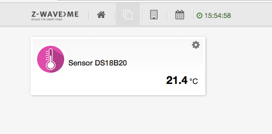
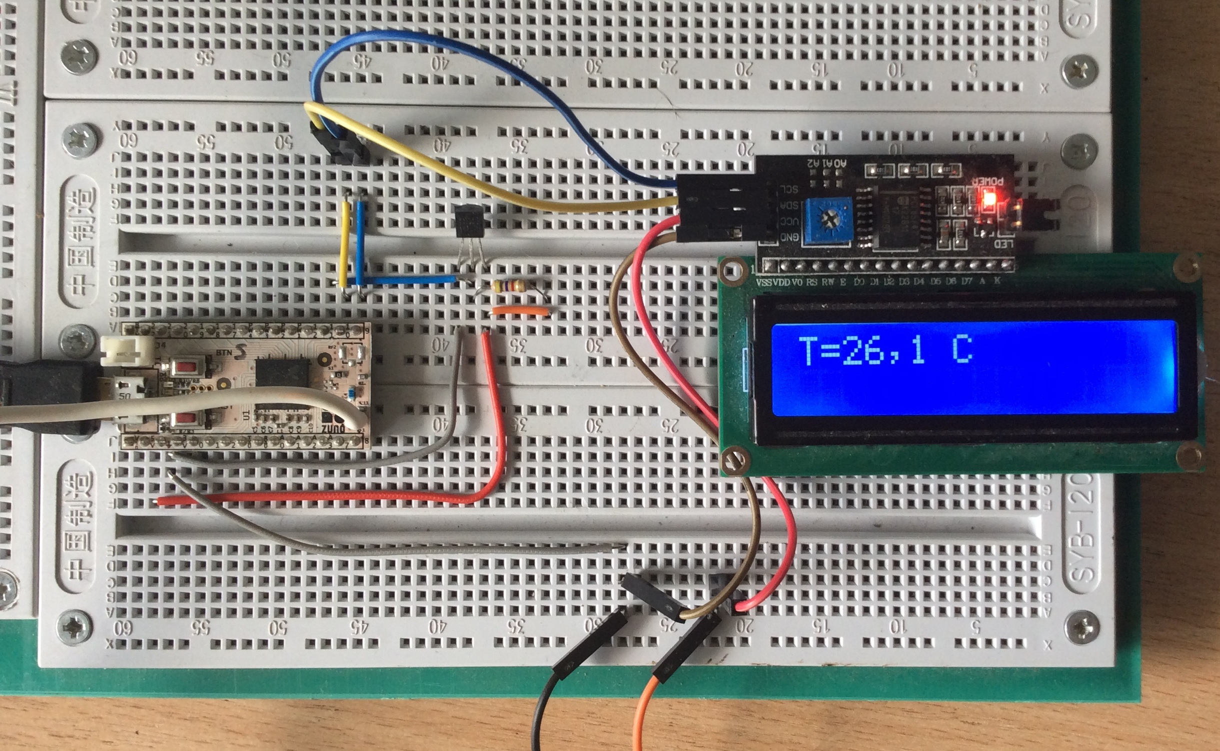
This sketch shows how to connect I2C LCD display and OneWire temperature sensor DS18B20 to the Z-Uno board. Temperature values is read from sensor, printed on the display and is periodically report to channel Multilevel Sensor.
Download Fritzing project
// demo sketch for connecting I2C LCD display and OneWire temperature sensor DS18B20 to Z-Uno

// add library Wire.h
#include "Wire.h"
#include "Print.h"

// add library ds18b20
#include "ZUNO_DS18B20.h"

// i2c address
#define LC_I2CADDR 0x27

// commands
#define LCD_CLEARDISPLAY 0x01
#define LCD_RETURNHOME 0x02
#define LCD_ENTRYMODESET 0x04
#define LCD_DISPLAYCONTROL 0x08
#define LCD_CURSORSHIFT 0x10
#define LCD_FUNCTIONSET 0x20
#define LCD_SETCGRAMADDR 0x40
#define LCD_SETDDRAMADDR 0x80

// flags for display entry mode
#define LCD_ENTRYRIGHT 0x00
#define LCD_ENTRYLEFT 0x02
#define LCD_ENTRYSHIFTINCREMENT 0x01
#define LCD_ENTRYSHIFTDECREMENT 0x00

// flags for display on/off control
#define LCD_DISPLAYON 0x04
#define LCD_DISPLAYOFF 0x00
#define LCD_CURSORON 0x02
#define LCD_CURSOROFF 0x00
#define LCD_BLINKON 0x01
#define LCD_BLINKOFF 0x00

// flags for display/cursor shift
#define LCD_DISPLAYMOVE 0x08
#define LCD_CURSORMOVE 0x00
#define LCD_MOVERIGHT 0x04
#define LCD_MOVELEFT 0x00

// flags for function set
#define LCD_8BITMODE 0x10
#define LCD_4BITMODE 0x00
#define LCD_2LINE 0x08
#define LCD_1LINE 0x00
#define LCD_5x10DOTS 0x04
#define LCD_5x8DOTS 0x00

// flags for backlight control
#define LCD_BACKLIGHT 0x08
#define LCD_NOBACKLIGHT 0x00

#define En 0x4  // Enable bit
#define Rw 0x2  // Read/Write bit
#define Rs 0x1  // Register select bit

int  cols;
int  rows;
int  numlines;
int  backlightval;
int  displayfunction;
int  displaycontrol;
int  displaymode;

// pin connection ds18b20
#define PIN_DS18B20 11
// add library OneWire
OneWire ow(11);
// onewire connection temperature sensors
DS18B20Sensor  ds1820(&ow);

byte addr1[8];
int temp;

// set up channel
ZUNO_SETUP_CHANNELS(
   ZUNO_SENSOR_MULTILEVEL(ZUNO_SENSOR_MULTILEVEL_TYPE_TEMPERATURE,
                          SENSOR_MULTILEVEL_SCALE_CELSIUS,
                          SENSOR_MULTILEVEL_SIZE_TWO_BYTES,
                          SENSOR_MULTILEVEL_PRECISION_ONE_DECIMAL,
                          getterTemp)
);

void setup() {
  Serial.begin();
  Serial.println("start");
  lcdbegin(16,2);
 }

void loop() {
    // obtaining readings from the sensor ds18b20
    temp=getTempds18b20();
    // print temp display
    printTempds18b20(temp);
    // send data to channel
    zunoSendReport(1);
    // send every 30 second
    delay(30000);
  }

int getTempds18b20() {
    // search OneWire device
    if(ds1820.scanAloneSensor(addr1)==1) {
       for(int i = 0; i < 8; i++) {
          // print OneWire kod
          Serial.print(addr1[i], HEX);
          Serial.print(" ");
          }
       Serial.println();
       Serial.print("t=");
       // receiving data from the sensor
       temp=ds1820.getTempC100(addr1)/10;
       Serial.println(temp);
       } else {
       Serial.println("error");
       temp=1000;
       }
    return temp;
    }

 word getterTemp() {
  return temp;
}


void printTempds18b20(int temp) {
  clear();
  setCursor(0,0);
  write('T');
  write('=');
  if(temp<100) {
     write(32);
  } else {
     write(temp/100+48);
  }
  write((temp%100)/10+48);
  write(44);
  write((temp%100)%10+48);
  write(32);
  write('C');
  return;
}

void lcdbegin(int c,int r) {
  //
  cols=c;
  rows=r;
  backlightval = LCD_BACKLIGHT;
  //
  Wire.begin();
  displayfunction = LCD_4BITMODE | LCD_1LINE | LCD_5x8DOTS;
  //
  if (rows > 1) {
    displayfunction |= LCD_2LINE;
  }
  numlines = rows;

  // SEE PAGE 45/46 FOR INITIALIZATION SPECIFICATION!
  // according to datasheet, we need at least 40ms after power rises above 2.7V
  // before sending commands. Arduino can turn on way befer 4.5V so we'll wait 50
  delay(50);

  // Now we pull both RS and R/W low to begin commands
  expanderWrite(backlightval); // reset expanderand turn backlight off (Bit 8 =1)
  delay(1000);

  //put the LCD into 4 bit mode
  // this is according to the hitachi HD44780 datasheet
  // figure 24, pg 46

   // we start in 8bit mode, try to set 4 bit mode
   write4bits(0x03 << 4);
   delayMicroseconds(4500); // wait min 4.1ms

   // second try
   write4bits(0x03 << 4);
   delayMicroseconds(4500); // wait min 4.1ms

   // third go!
   write4bits(0x03 << 4);
   delayMicroseconds(150);

   // finally, set to 4-bit interface
   write4bits(0x02 << 4);


  // set # lines, font size, etc.
  command(LCD_FUNCTIONSET | displayfunction);

  // turn the display on with no cursor or blinking default
  displaycontrol = LCD_DISPLAYON | LCD_CURSOROFF | LCD_BLINKOFF;
  display();

  // clear it off
  clear();

  // Initialize to default text direction (for roman languages)
  displaymode = LCD_ENTRYLEFT | LCD_ENTRYSHIFTDECREMENT;

  // set the entry mode
  command(LCD_ENTRYMODESET | displaymode);

  home();

  }

/********** high level commands, for the user! */
void clear(){
  command(LCD_CLEARDISPLAY);// clear display, set cursor position to zero
  delayMicroseconds(2000);  // this command takes a long time!
}

void home(){
  command(LCD_RETURNHOME);  // set cursor position to zero
  delayMicroseconds(2000);  // this command takes a long time!
}

void setCursor(uint8_t col, uint8_t row){
  int row_offsets[] = { 0x00, 0x40, 0x14, 0x54 };
  if ( row > numlines ) {
    row = numlines-1;    // we count rows starting w/0
  }
  command(LCD_SETDDRAMADDR | (col + row_offsets[row]));
}

// Turn the display on/off (quickly)
void noDisplay() {
  displaycontrol &= ~LCD_DISPLAYON;
  command(LCD_DISPLAYCONTROL | displaycontrol);
}
void display() {
  displaycontrol |= LCD_DISPLAYON;
  command(LCD_DISPLAYCONTROL | displaycontrol);
}


inline void command(uint8_t value) {
  send(value, 0);
}

inline size_t write(uint8_t value) {
  send(value, Rs);
  return 0;
}
/************ low level data pushing commands **********/

// write either command or data
void send(uint8_t value, uint8_t mode) {
  uint8_t highnib=value&0xf0;
  uint8_t lownib=(value<<4)&0xf0;
  write4bits((highnib)|mode);
  write4bits((lownib)|mode);
}

void write4bits(uint8_t value) {
  expanderWrite(value);
  pulseEnable(value);
}

void expanderWrite(uint8_t _data){
  Wire.beginTransmission(LC_I2CADDR);
  Wire.write((int)(_data) | backlightval);
  Wire.endTransmission();
}

void pulseEnable(uint8_t _data){
  expanderWrite(_data | En);  // En high
  delayMicroseconds(1);   // enable pulse must be >450ns

  expanderWrite(_data & ~En); // En low
  delayMicroseconds(50);    // commands need > 37us to settle
}
Download this sketch
	// demo sketch for connecting I2C LCD display and OneWire temperature sensor DS18B20 to Z-Uno

	// add library Wire.h
	#include "Wire.h"
	#include "Print.h"

	// add library ds18b20
	#include "ZUNO_DS18B20.h"

	// i2c address
	#define LC_I2CADDR 0x27

	// commands
	#define LCD_CLEARDISPLAY 0x01
	#define LCD_RETURNHOME 0x02
	#define LCD_ENTRYMODESET 0x04
	#define LCD_DISPLAYCONTROL 0x08
	#define LCD_CURSORSHIFT 0x10
	#define LCD_FUNCTIONSET 0x20
	#define LCD_SETCGRAMADDR 0x40
	#define LCD_SETDDRAMADDR 0x80

	// flags for display entry mode
	#define LCD_ENTRYRIGHT 0x00
	#define LCD_ENTRYLEFT 0x02
	#define LCD_ENTRYSHIFTINCREMENT 0x01
	#define LCD_ENTRYSHIFTDECREMENT 0x00

	// flags for display on/off control
	#define LCD_DISPLAYON 0x04
	#define LCD_DISPLAYOFF 0x00
	#define LCD_CURSORON 0x02
	#define LCD_CURSOROFF 0x00
	#define LCD_BLINKON 0x01
	#define LCD_BLINKOFF 0x00

	// flags for display/cursor shift
	#define LCD_DISPLAYMOVE 0x08
	#define LCD_CURSORMOVE 0x00
	#define LCD_MOVERIGHT 0x04
	#define LCD_MOVELEFT 0x00

	// flags for function set
	#define LCD_8BITMODE 0x10
	#define LCD_4BITMODE 0x00
	#define LCD_2LINE 0x08
	#define LCD_1LINE 0x00
	#define LCD_5x10DOTS 0x04
	#define LCD_5x8DOTS 0x00

	// flags for backlight control
	#define LCD_BACKLIGHT 0x08
	#define LCD_NOBACKLIGHT 0x00

	#define En 0x4  // Enable bit
	#define Rw 0x2  // Read/Write bit
	#define Rs 0x1  // Register select bit

	int  cols;
	int  rows;
	int  numlines;
	int  backlightval;
	int  displayfunction;
	int  displaycontrol;
	int  displaymode;

	// pin connection ds18b20
	#define PIN_DS18B20 11
	// add library OneWire
	OneWire ow(11);
	// onewire connection temperature sensors
	DS18B20Sensor  ds1820(&ow);

	byte addr1[8];
	int temp;

	// set up channel
	ZUNO_SETUP_CHANNELS(
	   ZUNO_SENSOR_MULTILEVEL(ZUNO_SENSOR_MULTILEVEL_TYPE_TEMPERATURE,
							  SENSOR_MULTILEVEL_SCALE_CELSIUS,
							  SENSOR_MULTILEVEL_SIZE_TWO_BYTES,
							  SENSOR_MULTILEVEL_PRECISION_ONE_DECIMAL,
							  getterTemp)
	);

	void setup() {
	  Serial.begin();
	  Serial.println("start");
	  lcdbegin(16,2);
	 }

	void loop() {
		// obtaining readings from the sensor ds18b20
		temp=getTempds18b20();
		// print temp display
		printTempds18b20(temp);
		// send data to channel
		zunoSendReport(1);
		// send every 30 second
		delay(30000);
	  }

	int getTempds18b20() {
		// search OneWire device
		if(ds1820.scanAloneSensor(addr1)==1) {
		   for(int i = 0; i < 8; i++) {
			  // print OneWire kod
			  Serial.print(addr1[i], HEX);
			  Serial.print(" ");
			  }
		   Serial.println();
		   Serial.print("t=");
		   // receiving data from the sensor
		   temp=ds1820.getTempC100(addr1)/10;
		   Serial.println(temp);
		   } else {
		   Serial.println("error");
		   temp=1000;
		   }
		return temp;
		}

	 word getterTemp() {
	  return temp;
	}


	void printTempds18b20(int temp) {
	  clear();
	  setCursor(0,0);
	  write('T');
	  write('=');
	  if(temp<100) {
		 write(32);
	  } else {
		 write(temp/100+48);
	  }
	  write((temp%100)/10+48);
	  write(44);
	  write((temp%100)%10+48);
	  write(32);
	  write('C');
	  return;
	}

	void lcdbegin(int c,int r) {
	  //
	  cols=c;
	  rows=r;
	  backlightval = LCD_BACKLIGHT;
	  //
	  Wire.begin();
	  displayfunction = LCD_4BITMODE | LCD_1LINE | LCD_5x8DOTS;
	  //
	  if (rows > 1) {
		displayfunction |= LCD_2LINE;
	  }
	  numlines = rows;

	  // SEE PAGE 45/46 FOR INITIALIZATION SPECIFICATION!
	  // according to datasheet, we need at least 40ms after power rises above 2.7V
	  // before sending commands. Arduino can turn on way befer 4.5V so we'll wait 50
	  delay(50);

	  // Now we pull both RS and R/W low to begin commands
	  expanderWrite(backlightval); // reset expanderand turn backlight off (Bit 8 =1)
	  delay(1000);

	  //put the LCD into 4 bit mode
	  // this is according to the hitachi HD44780 datasheet
	  // figure 24, pg 46

	   // we start in 8bit mode, try to set 4 bit mode
	   write4bits(0x03 << 4);
	   delayMicroseconds(500); // wait min 4.1ms
	   delay(4);

	   // second try
	   write4bits(0x03 << 4);
	   delayMicroseconds(500); // wait min 4.1ms
	   delay(4);

	   // third go!
	   write4bits(0x03 << 4);
	   delayMicroseconds(150);

	   // finally, set to 4-bit interface
	   write4bits(0x02 << 4);


	  // set # lines, font size, etc.
	  command(LCD_FUNCTIONSET | displayfunction);

	  // turn the display on with no cursor or blinking default
	  displaycontrol = LCD_DISPLAYON | LCD_CURSOROFF | LCD_BLINKOFF;
	  display();

	  // clear it off
	  clear();

	  // Initialize to default text direction (for roman languages)
	  displaymode = LCD_ENTRYLEFT | LCD_ENTRYSHIFTDECREMENT;

	  // set the entry mode
	  command(LCD_ENTRYMODESET | displaymode);

	  home();

	  }

	/********** high level commands, for the user! */
	void clear(){
	  command(LCD_CLEARDISPLAY);// clear display, set cursor position to zero
	  delay(2);  // this command takes a long time!
	}

	void home(){
	  command(LCD_RETURNHOME);  // set cursor position to zero
	  delay(2);  // this command takes a long time!
	}

	void setCursor(uint8_t col, uint8_t row){
	  int row_offsets[] = { 0x00, 0x40, 0x14, 0x54 };
	  if ( row > numlines ) {
		row = numlines-1;    // we count rows starting w/0
	  }
	  command(LCD_SETDDRAMADDR | (col + row_offsets[row]));
	}

	// Turn the display on/off (quickly)
	void noDisplay() {
	  displaycontrol &= ~LCD_DISPLAYON;
	  command(LCD_DISPLAYCONTROL | displaycontrol);
	}
	void display() {
	  displaycontrol |= LCD_DISPLAYON;
	  command(LCD_DISPLAYCONTROL | displaycontrol);
	}


	inline void command(uint8_t value) {
	  send(value, 0);
	}

	inline size_t write(uint8_t value) {
	  send(value, Rs);
	  return 0;
	}
	/************ low level data pushing commands **********/

	// write either command or data
	void send(uint8_t value, uint8_t mode) {
	  uint8_t highnib=value&0xf0;
	  uint8_t lownib=(value<<4)&0xf0;
	  write4bits((highnib)|mode);
	  write4bits((lownib)|mode);
	}

	void write4bits(uint8_t value) {
	  expanderWrite(value);
	  pulseEnable(value);
	}

	void expanderWrite(uint8_t _data){
	  Wire.beginTransmission(LC_I2CADDR);
	  Wire.write((int)(_data) | backlightval);
	  Wire.endTransmission();
	}

	void pulseEnable(uint8_t _data){
	  expanderWrite(_data | En);  // En high
	  delayMicroseconds(1);   // enable pulse must be >450ns

	  expanderWrite(_data & ~En); // En low
	  delayMicroseconds(50);    // commands need > 37us to settle
	}
Download this sketch